Transform your telecom applications with multi-networking and Kubernetes
Ramesh Nagarajan
Ramesh Nagarajan, Head of Network Monetization & Strategic Partnerships for Telecommunications, Google Cloud
Vlad Moldoveanu
Engineering Manager, GDC Solutions
Traditional Kubernetes networking excels at basic Pod-to-Pod connectivity, but can fall short when addressing the security, performance, and compliance demands of telecom workloads. This limits telecom providers’ ability to fully leverage Kubernetes’ scalability and agility benefits.
Google Cloud's multi-networking approach empowers telecom providers to overcome these limitations, enabling capabilities such as but not limited to:
-
Strict network isolation: Enforce regulatory compliance and enhance security by isolating management, signaling, and media traffic within Kubernetes.
-
Maximum performance: For telecom applications that need hardware acceleration (e.g., SR-IOV), achieve the high throughput and low latency you need for demanding 5G Mobile Core, RAN, and data-plane workloads.
There are existing solutions such as Multus, a meta-plugin for multi-homed Pods in Kubernetes, but it has some drawbacks:
-
Difficult to use: Multus relies on unstructured string-based annotations, making configuration complex and error-prone.
-
Inflexible: It doesn't allow for dynamic addition or removal of networks to Pods, creating operational overhead and limiting adaptability.
-
Limited Kubernetes integration: Multus lacks native support for
-
Network Policies: Enforcing security across multiple networks is difficult.
-
Network Services: Load balancing and health checks for applications using secondary interfaces are unsupported.
-
-
Poor observability: Multus makes it hard to monitor and troubleshoot multi-network setups.
Google Cloud's approach natively integrates multi-networking into Kubernetes. This makes it easy to use Kubernetes services, load balancers, Border Gateway Protocol (BGP), and network policies – all vital for building robust telecom networks. We’re also working on this concept with the Kubernetes community as part of a Kubernetes Enhancement Proposal in the Cloud Native Computing Foundation (CNCF).
Partners such as Ericsson are supportive of Google Cloud’s multi-networking approach with a focus on addressing the specific needs of telecom use cases.
“The challenge of ensuring security and operational efficiency in telecom deployments through network separation, while preserving Kubernetes' standard networking capabilities, is solved by Google's multi-network function. It's noteworthy to observe how Google's multi-network function provides a solution to this challenge without compromising on functionality.” - Ericsson
In this blog, we explore critical telecom use cases enabled by multi-networking. We also delve into two specific implementation examples in Google Distributed Cloud (GDC): isolating signaling traffic between a Mobility Management Entity (MME) and Home Subscriber Server (HSS) in a 4G/5G mobile core deployment as well as for isolating signaling traffic between the Network Exposure Function (NEF) and its Application Function (AF) peer.
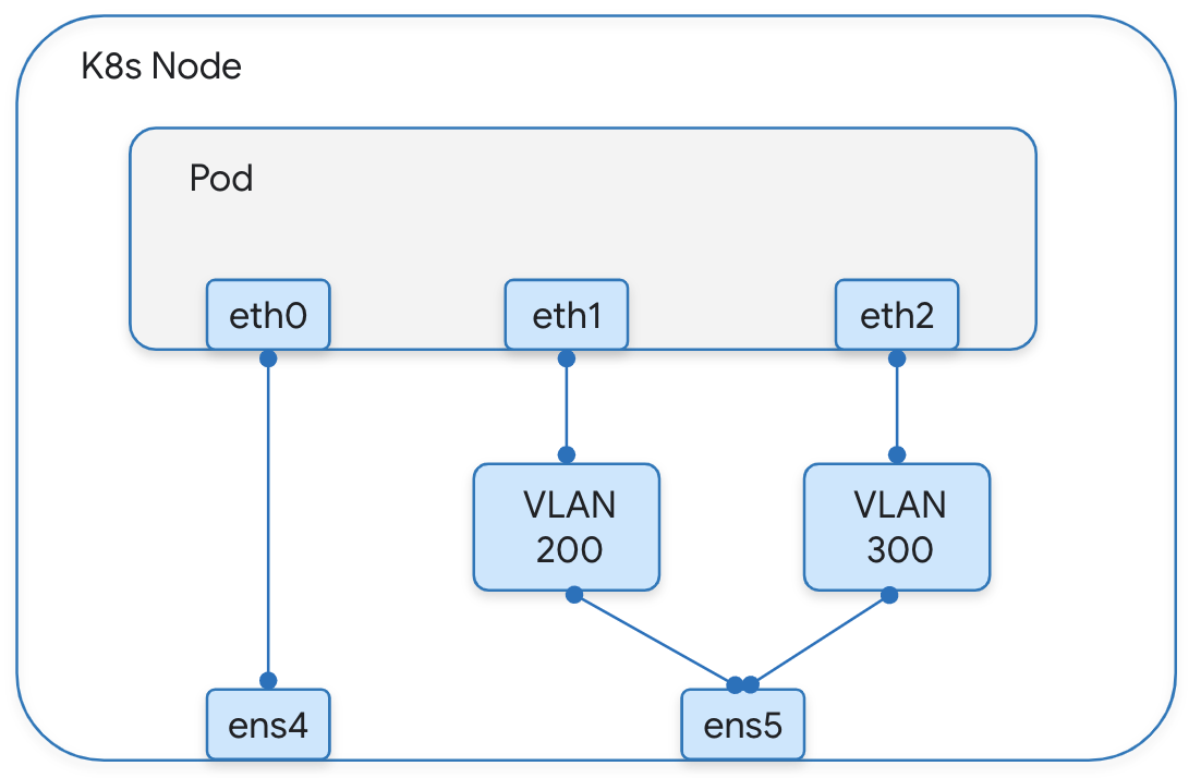
Multi-network use case #1
A Cloud Native Network Function (CNF) application requires an additional interface to be provisioned into its Kubernetes pod. Each of these interfaces has to be in an isolated network for regulatory compliance purposes. The isolation has to be done on a Layer-2 network.

Multi-networking use case #2
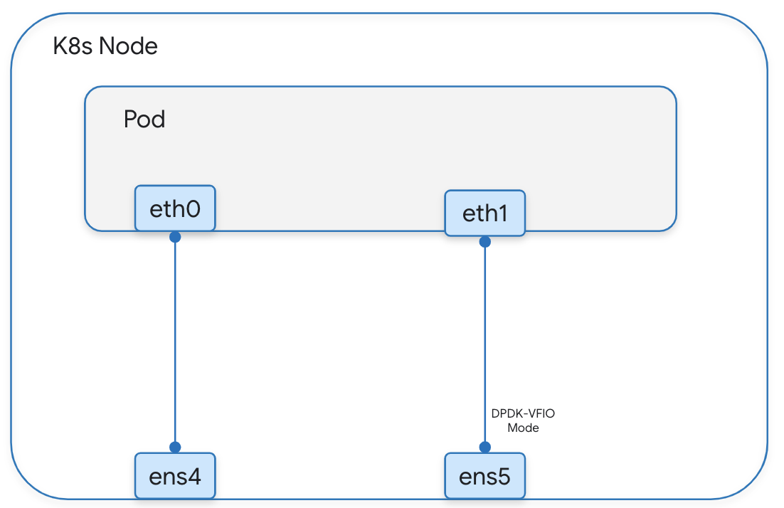
A CNF application requires a hardware-based interface (e.g., SR-IOV VF) to be provisioned to the workload Pod. The hardware will be leveraged by the user-space application (e.g. DPDK-based) for performance purposes (high bandwidth, low latency).

Application of multi-networking for a 4G/5G networking scenario
Multi-network use case: S6a Traffic
Now, let’s take a look at a specific use of the multi-network framework for networking between an Mobility Management Entity (MME) and Home Subscriber Server (HSS) function of a 4G mobile core network. In a 4G mobile network, the MME and the HSS are key network elements responsible for managing user connectivity and security:
-
MME:
-
Handles user attach/detach procedures, registering and deregistering devices on the network
-
Manages handovers between cell towers as users move around
-
Routes incoming and outgoing calls and data traffic to/from the user
-
-
HSS:
-
Stores subscriber information like authentication credentials, subscription details, and roaming agreements
-
Performs authentication and authorization procedures to verify user identity and access control
-
Provides user location information to the MME for emergency services and other purposes
-
Together, the MME and HSS provide a secure and smooth user experience while maintaining network efficiency and subscriber information integrity.
This connectivity scenario highlights a specific application of use case #1 above for purposes of connecting the MME and HSS Pods via an isolated signaling network using GDC in connected configuration which provides a fully managed hardware and software product that delivers modern applications equipped with AI, security, and open source at the edge. In this implementation, the MME uses a MACVLAN type of interface and the HSS Pods use a separate multi-network interface to steer the Diameter traffic onto the same signaling network.
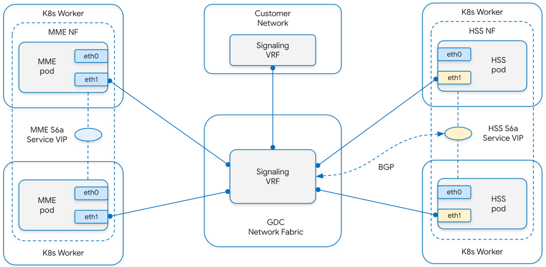

Here’s a snippet of the signaling network definition and the modified HSS Pod spec to reference this additional Pod network on the respective Pods:
Multinetwork use case for N33 interface on NEF
Now, let’s look at a specific use of the multi-network framework for networking between a Network Exposure Function (NEF) and its Application Function (AF) Peer — two nodes in the 5G Network Architecture:
-
NEF - This network function provides a means to securely expose the services and capabilities provided by 3GPP network functions to application
-
AF Peer - This network function plays a key role in traffic management and QoS assignments.
In this scenario, the AF Peer of NEF resides in the customer’s trusted domain and is connected to the Signaling network (VRF). By default, the NEF Pods are connected to the default network (VRF) via their primary interface. In order to keep the traffic onto the same VRF, we enable signaling multi-networking on the NEF pods to connect them to the Signaling network.
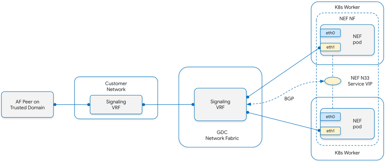

For the above two use cases, the 3GPP endpoints of the HSS or NEF respectively, illustrated as Service VIPs (Virtual IPs), are exposed as Service type: LoadBalancer using the bundled BGP load balancer in GDC. This is a BGP-based L3 load balancer. It includes a BGP speaker as control plane and an eBPF based datapath. The BGP speaker automatically advertises Service IPs from Kubernetes Service (type=LoadBalancer) to the configured eBGP peers. The eBPF-based datapath then distributes the incoming Service VIP traffic to the backend pods.
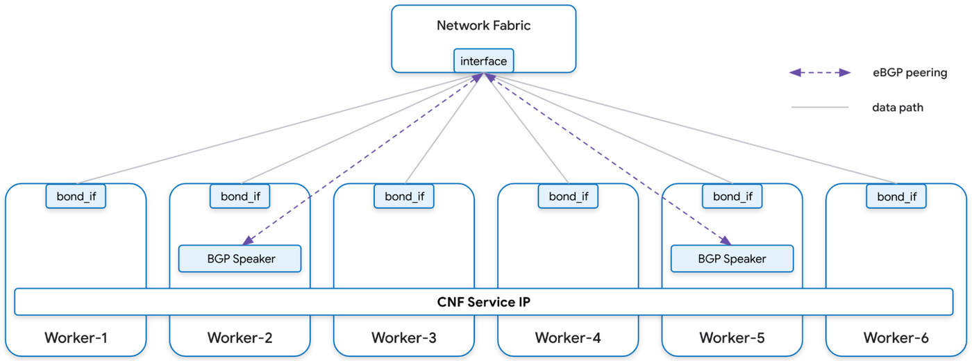

Here’s a snippet of the load balancer spec:
And here we can see the config-map spec that allows us to deterministically choose the External IPs to be allocated to the 3GPP Services VIPs.
Empowering telecom providers with multi-networking
In this blog, we showed how Google Cloud’s multi-networking approach can unlock critical telecom use cases on Kubernetes. To learn more about using Google Distributed Cloud and GKE for telecom workloads, check out the following resources:
- Kubernetes Enhancement Proposal for Multi-network, KEP-3698 Multi-network
- Google Distributed Cloud overview: Google Distributed Cloud
- Using Network Function Optimizer for GKE and GDC: Network Function Optimizer for GKE and GDC Edge
- Multinetwork support and configuration in GKE: About the multi-network support for Pods | Google Kubernetes Engine (GKE)
- Multinetwork Support and Configuration in GDC: Network Function operator | Distributed Cloud


